| System | Description |
| Root axes | Fixed to the blade root, and it does not rotate with twist or blade deflection but rotates about the z-axis with pitch. |
| Chord axes | Located at the leading edge of the aerofoil and follows the Aerodynamic twist. |
| Principal elastic axes | Located at the Elastic centre and follows the Principal elastic axes orientation (xe, ye). |
| Principal shear axes | Located at the Shear centre and follows the Principal shear axes orientation (xs, ys) . |
| Principal inertia axes | Located at the Mass centre and follows the Principal inertia axes orientation (xm, ym) . |
| User axis | Located at the User axis , specified by the user for additional loads output. See Loads Outputs at User Axes for details. |
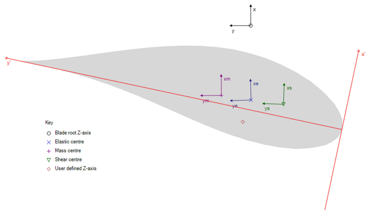
Figure 2: Overview of blade section coordinate systems in Bladed.
# Definition of Centre Locations and Axes Orientations
The centres, including the Elastic centre, Shear centre, Mass centre and User axis,are all defined with respect to the chord axes, which are controlled by the Aerodynamic twist . The
locations of these centres are specified as a percentage of the chord length measured from the aerofoil leading edge. An example of this is illustrated in Figure 3 for the Shear centre definition.

Figure 3: Top: Definition of shear centre (x'). Bottom: Definition of Shear centre (y').
Furthermore,the orientations of the Aerodynamic twist , Principal elastic axes orientation (xe, ye), Principal shear axes orientation (xs, ys),and Principal inertia axes orientation (xm, ym) are all defined with respect to the root axes and are positive in the clockwise direction as shown in Figure 4. In the GUl, the unit of the inputs is in degrees, whereas in the project file, it is in radians.

Figure 4: Definition of various property axes orientations in Bladed.
# Overview of Blade Section Inputs and Associated Coordinate Systems
This section provides an overview of the structural properties defined in the various coordinate systems. For more details, see Blade Section Stiffness and Blade Section Mass.
# Principal Elastic Axes
The following blade section input properties are defined in the principal elastic axes coordinate system:
Bending stiffness about xe
Bending stiffness about ye
Shear stiffness along xe
Shear stiffness along ye
Axial stiffness
FlapEdgeCStiff
TorsionFlapCStiff
TorsionEdgeCStiff
# Principal Shear Axes
The following blade section input property is defined in the principal shear axes coordinate system:
Torsional stiffness
The following blade section input properties are defined in the principal inertia axes coordinate system:
Mass/unit length
Polar mass moment of inertia/unit length
Radii of gyration ratio
# Chord Axes
The following blade section input properties are defined in the chord axes coordinate system:
Chord Thickness Foil section
Last updated 16-12-2024
# Blade Section Geometry
The blade geometry is defined for each blade station. Select the option at the bottom of the screen to specify either the distance along blade or distance along blade root Z-axis .The alternate value will be automatically calculated using the neutral axis values. For example, selecting Distance along blade will automatically calculate the Distance along blade root Zaxis , and vice versa. For details refer to the section on Distance Along Blade. The following geometry data is required at each blade station:
Table 1: Overview over required geometry parameters for blade definition in Bladed
Variable identifier Unit Description
| Distance along blade | m | The distance from the blade root to the current station along the neutral axis, which may not be straight. It must be zero for the first station. |
| Distance along blade root Z-axis | m | The distance of the blade station along the blade root Z-axis. |
| Chord | m | The distance from the leading edge to the trailing edge along the chord line. |
| | Aerodynamic twist deg The local angle of the chord line. More positive values of twist and set angle push the leading edge further upwind in the direction from which the flow is coming. |
| Thickness | % | The thickness of the blade as a percentage of the chord at that station. |
| Neutral axis (x) | m | The distance from the blade root Z-axis to the neutral axis in the x- direction. This would be non-zero if, for example, the blade was pre- bent. |
| Neutral axis (y) | m | The distance from the blade root Z-axis to the neutral axis in the y- direction. |
| Elastic centre (x') | % | The distance from the leading edge to the elastic centre along the chord x-axis, as a percentage of the chord. |
| Elastic centre (y') | % | The distance from the leading edge to the elastic centre along the chord y-axis, as a percentage of the chord. |
| Foil section | | An index number defining the aerofoil section at that station. |
| Moving/Fixed | | Differentiates between fixed and movable parts of the blade for pitch of that part of the blade, or by deploying an aileron, flap or other aerodynamic control surfaces. |
Figure 1 and Figure 2 illustrate a blade station for Clockwise and Anticlockwise rotor configurations. It is assumed that the perspective is from the tip toward the root, aligned to the root axes plane.
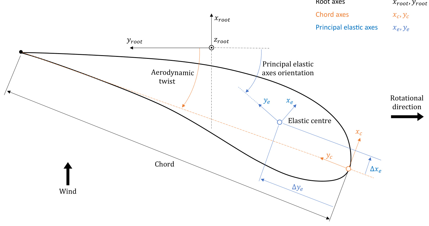
Figure 1: Aerofoil at a blade station illustrating root axes, principal elastic axes and chord axes.
# Anticlockwise Rotors
The blade inputs for an Anticlockwise rotor use a left-handed coordinate system, in contrast to the right-handed system for clockwise rotors. As a result, no changes are needed to the input data when switching between Clockwise and Anticlockwise rotors. See Figure 2 for an illustration of the Anticlockwise blade definition.
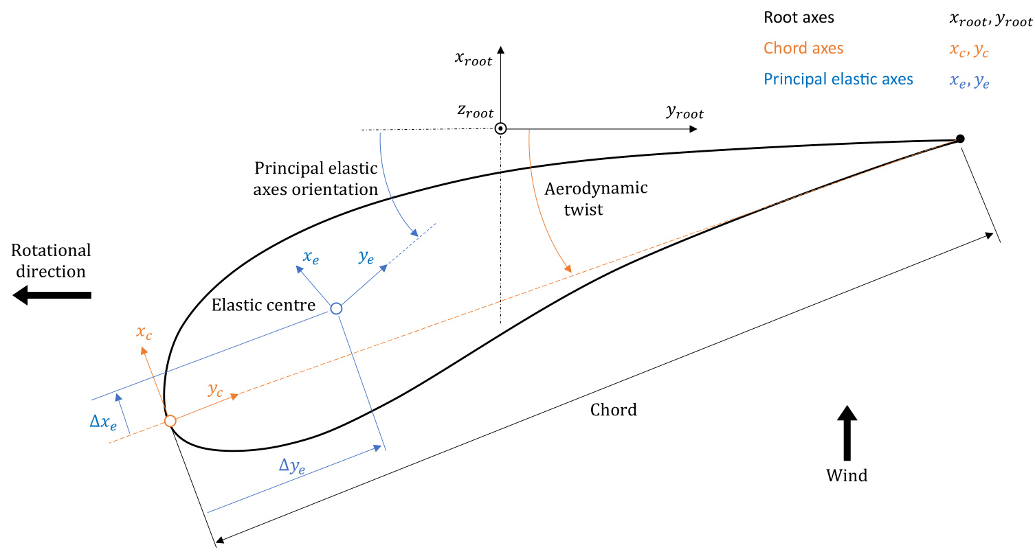
Figure 2: Anticlockwise rotating blade station, where the left-handed coordinate system ensures compatibility when switching between rotor directions.
# Blade Section Stiffness
To model flexible blades or analyse vibrational dynamics, it is necessary to define the stiffness distribution of the rotor blade. Begin by selecting the appropriate degrees of freedom to include in the model by enabling/disabling the following options in the Blades screen under the Mass and Stiffnesstab:
Bending stiffness
Shear stiffness
Torsional degree of freedom
Axial degree of freedom
It is also possible to include bend-twist and bending-bending couplingterms, and these can be defined using Project info .
# Constitutive Relationship
The blade sectional stiffness inputs all relate to the cross-sectional $6\!\times\!6$ stiffness matrix used in the Bladed beam model as shown in Equation (1). This matrix is associated with the principal elastic axes coordinate system, which is defined by the Principal elastic axes orientation (xe, ye) and the Elastic centre as described in Blade Section Coordinate Systems. The constitutive relationship for the full beam model can be expressed as:
$$
\left[\begin{array}{c}{F_{x}}\\ {F_{y}}\\ {F_{z}}\\ {M_{x}}\\ {M_{y}}\\ {M_{z}}\end{array}\right]=\left[\begin{array}{c c c c c c c}{G A_{x}}&&&&{\left|}&&&\\ {G A_{x y}}&&{G A_{y}}&&&{\left|}&&{\mathrm{sym}}\\ {0}&{0}&&{E A}&{\left|}&&&\\ {-}&{-}&{-}&{-}&{-}&{-}&{-}&{-}\\ {0}&{0}&{0}&{\left|}&{E I_{x}}&&\\ {0}&{0}&{0}&{\left|}&{C_{x y}}&{E I_{y}}\\ {-G A_{x}y_{c s}}&{G A_{y}x_{c s}}&{0}&{\left|}&{C_{x z}}&{C_{y z}}&{G I_{z}}\right.\right]\left[\kappa_{z}\right]
$$
where
$$
G I_{z}=G I_{z}^{*}+G A_{x}\cdot y_{c s}^{2}+G A_{y}\cdot x_{c s}^{2}
$$
$\mathbf{\boldsymbol{x}}_{c s}$ and $y_{c s}$ are the offsets between the Elastic centre and shear centre along the principal elastic axes.
Table 1: Overview of blade sectional stiffness inputs in Bladed, relating them to Equation (1).
| Property | Variable | Description | Unit | Input Location |
| Bending stiffness about xe | EIc | Bending stiffness about the principal elastic x-axis | Nm2 | Blades |
| screen |
| Bending stiffness about ye | EIy | Bending stiffness about the principal elastic y-axis | Nm2 | Blades |
| Torsional stiffness | GI* | Torsional stiffness about the principal | Nm2 | screen Blades |
| about zs | | shear z-axis (shear centre) | | screen |
| Shear stiffness along xe | GAx | Shear stiffness along the principal elastic x-axis | N | Blades |
| Shear stiffness along | GAy | Shear stiffness along the principal | N | screen Blades |
| ye | | elastic y-axis | | screen |
| Axial stiffness | EA | Axial stiffness of cross-section | N | Blades |
| FlapEdgeCStiff | Cry | Bending-Bending coupling stiffness | Nm2 | screen |
| | along principal elastic x- and y-axes | | Project Info |
| TorsionFlapCStiff | Ccz | Torsion-Bending coupling stiffness | Nm2 | Project |
| | | | |
| | | | |
| | | | |
| | along principal elastic x-axes | | Info |
| | | | |
| | | | |
| TorsionEdgeCStiff | yz | Torsion-Bending coupling stiffness along principal elastic y-axis | Nm2 | Project Info |
# $\textcircled{i}$ NOTE
The shear-shear coupling stiffness $G A_{x y}$ and shear-twist coupling stiffness terms $G A_{x}y_{c s}$ and $G A_{y}{\pmb x}_{c s}$ are calculated automatically by Bladed based on the input values.
# Project Info Definition of Bending-Twist and Bending-Bending Coupling Terms
Bending-twist and bending-bending coupling terms can be specified through Project Info. More details on how the inputs are used in the simulation can be found in the theory article Bend-Twist Coupling Relationships in Beam Elements.
You need enough entries for the number of elements in the blade. Each node in the Bladed user interface defines the properties for both the end of one element and the beginning of the next, unless it is a split station so there must be $2N_{e l}-2$ entries, where $N_{e l}$ is the number of blade elements.
MSTART EXTRA
TorsionEdgeCStiff $^*$ list of values TorsionFlapCStiff \* list of values FlapEdgeCStiff \* list of values MEND
For example, for the demo_a turbine (which has 10 blade stations):
# MSTART EXTRA
Torsi0nEdgeCStiff 10000.0 10000.0 10000.0 10000.0 10000.0 10000.0 10000.0 10000.0 10000.0
10000.0 10000.0 10000.0 10000.0 10000.0 10000.0 10000.0 10000.0 10000.0
TorsionFlapCStiff 10000.0 10000.0 10000.0 10000.0 10000.0 10000.0 10000.0 10000.0 10000.0
10000.0 10000.0 10000.0 10000.0 10000.0 10000.0 10000.0 10000.0 10000.0
FlapEdgeCStiff 10000.0 10000.0 10000.0 10000.0 10000.0 10000.0 10000.0 10000.0 10000.0
10000.0 10000.0 10000.0 10000.0 10000.0 10000.0 10000.0 10000.0 10000.0
MEND
Last updated 05-12-2024
# Blade Section Mass
To accurately model the dynamic behavior of rotor blades, it is essential to define their mass and inertia distribution.This is primarily done in the Blades screen under the Mass and Stiffness tab by enabling the Mass checkbox. Additional options are available to model point masses and blade icing:
Additional Mass/Inertia Ice on blades
It is also possible to define blade Imbalances and Vibration Dampers, which add to the total blade mass.
# Blade Mass and Inertia Distribution
The following table provides an overview of the inputs required to define the blade sectional mass distribution at each blade station.
Table 1: Overview of blade sectional mass distribution inputs in Bladed